03 · May 2026
Fan drive transmission system
Course project for Machine Design Fundamentals at Warsaw University of Technology. A belt-driven fan drive: motor and V-belt selection, shaft strength calculations, bearing selection and frame analysis, plus a full set of manufacturing drawings and a 3D assembly model.
Specifications
- Useful power
- 1.15 kW
- Rotational speed
- 1100 rpm
- Transmission
- V-belt, type HA, 2 belts
- Bearings
- SKF 2307 ETN9 (self-aligning)
- Required life
- L₁₀ₕ = 125,000 h
- Shaft material
- C35, 170–190 HB
3D model — drive assembly
Drag to orbit · click first, then scroll to zoom
Loading model…
Could not load the 3D model
Project goal
A course project for Machine Design Fundamentals at the Faculty of Power and Aeronautical Engineering, Warsaw University of Technology. In it I designed a complete belt-driven fan drive. I started from the input data, selected the standard components, did the strength calculations and finished with a set of drawings ready for manufacture.
| Input parameter | Symbol | Value |
|---|---|---|
| Useful power | P | 1.15 kW |
| Rotational speed | n | 1100 rpm |
| Required bearing life | L₁₀ₕ | 125,000 h |
| Axial force | FW | 310 N |
| Fan weight | FQ | 135 N |
Methodology
Motor and belt drive selection
I worked out the power needed from the motor from the drivetrain efficiencies (ηpp = 0.93 for the belt drive, ηb = 0.99 per bearing pair). I chose a type HA V-belt drive with a 125 mm pitch diameter driving pulley (D₁ₛ), which gives a belt speed of about 10 m/s. One belt is rated at P₀ = 2 kW; after the correction factors for belt length and wrap angle (kl = kα = 0.99), two belts were needed.
Drive shaft analysis
I treated the shaft as a beam on two supports, one fixed and one sliding. It carries the axial force, the fan’s weight and moment, and the force and moment from the belt drive. I checked, in order:
- statics and the internal load distribution,
- static strength,
- deflection and critical speed,
- fatigue strength at three critical sections (two shoulders and the keyway under the fan hub), including notch effects,
- the keys, sized from the allowable surface pressure.
Bearings and frame
I used SKF 2307 ETN9 self-aligning ball bearings, because they absorb misalignment from shaft deflection and assembly errors. One support locates the shaft and the other floats: the housing on the fan side holds it axially, while the one by the pulley can slide, so thermal expansion doesn’t load the bearings. TSN 509A V-rings do the sealing. I analysed the welded frame statically and checked it with a preliminary FEA.
Results
| Quantity | Result |
|---|---|
| Number of V-belts | 2 (type HA) |
| Theoretical bearing life | 2,124,409 h |
| Required life | 125,000 h |
| Fatigue safety margin | ≥ 8 × the assumed factor n = 1.5 |
| Shaft length | 472.5 mm |
The most interesting part was what actually set the shaft diameters. Static strength alone allowed much smaller diameters than the ones I ended up with; shaft deflection and the required bearing life decided them. That is why the fatigue safety factors came out at least eight times higher than required.
Materials
| Material | Standard | Application |
|---|---|---|
| S235JR | PN-EN 10025:2002 | frame, threaded bushings, shim plates |
| C35 | PN-EN 10083-2 | drive shaft, spacer bushings |
| C45 | PN-EN 10083-2 | keys |
| PN-GJL 200 | PN-EN 1561:2000 | belt drive pulleys (cast) |
Documentation
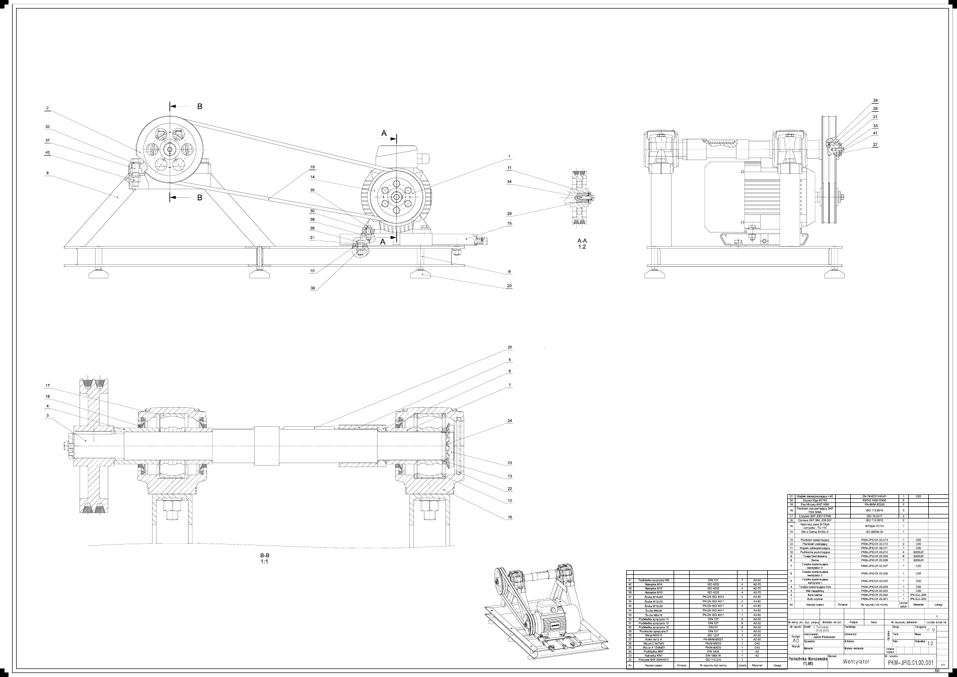
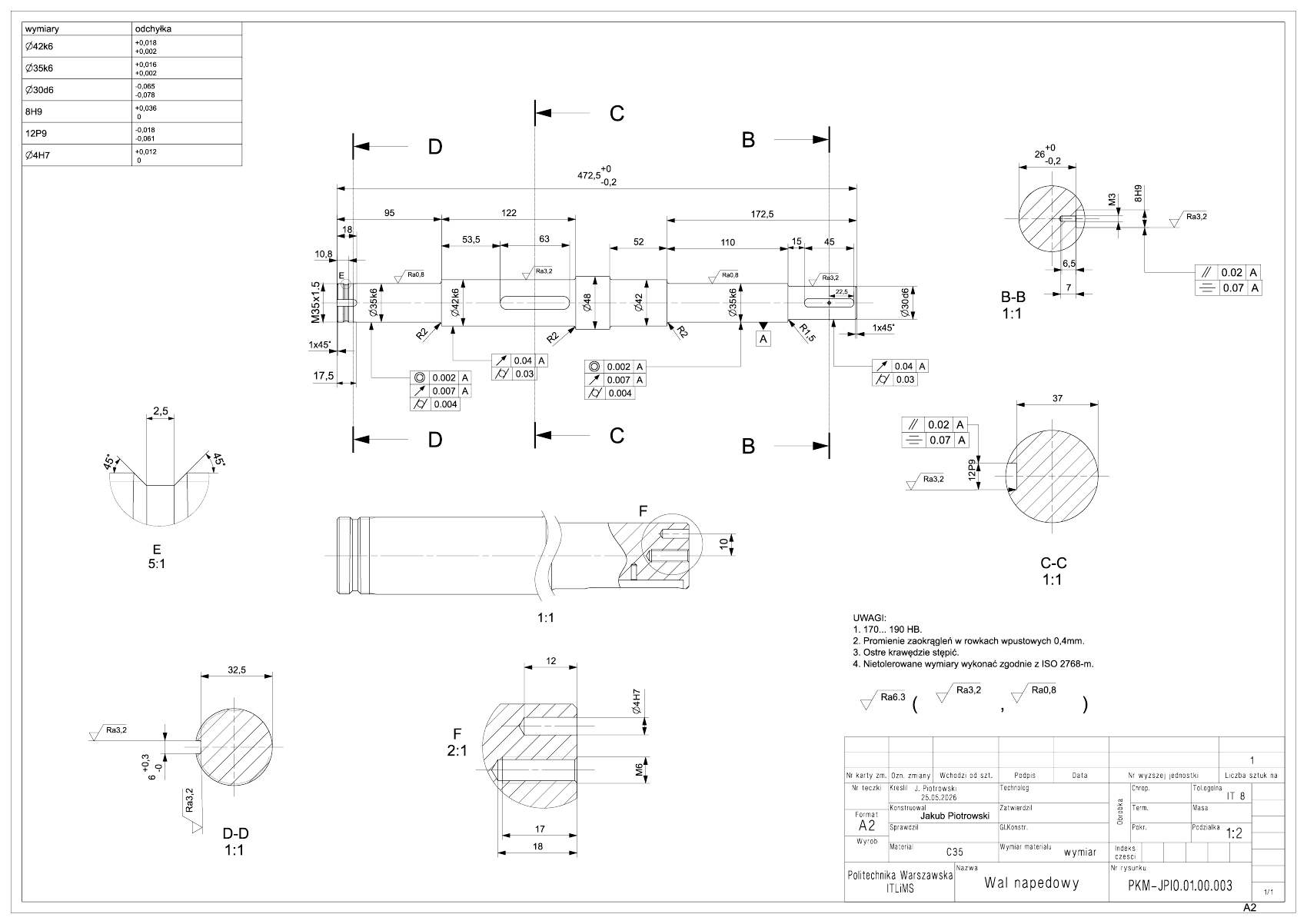
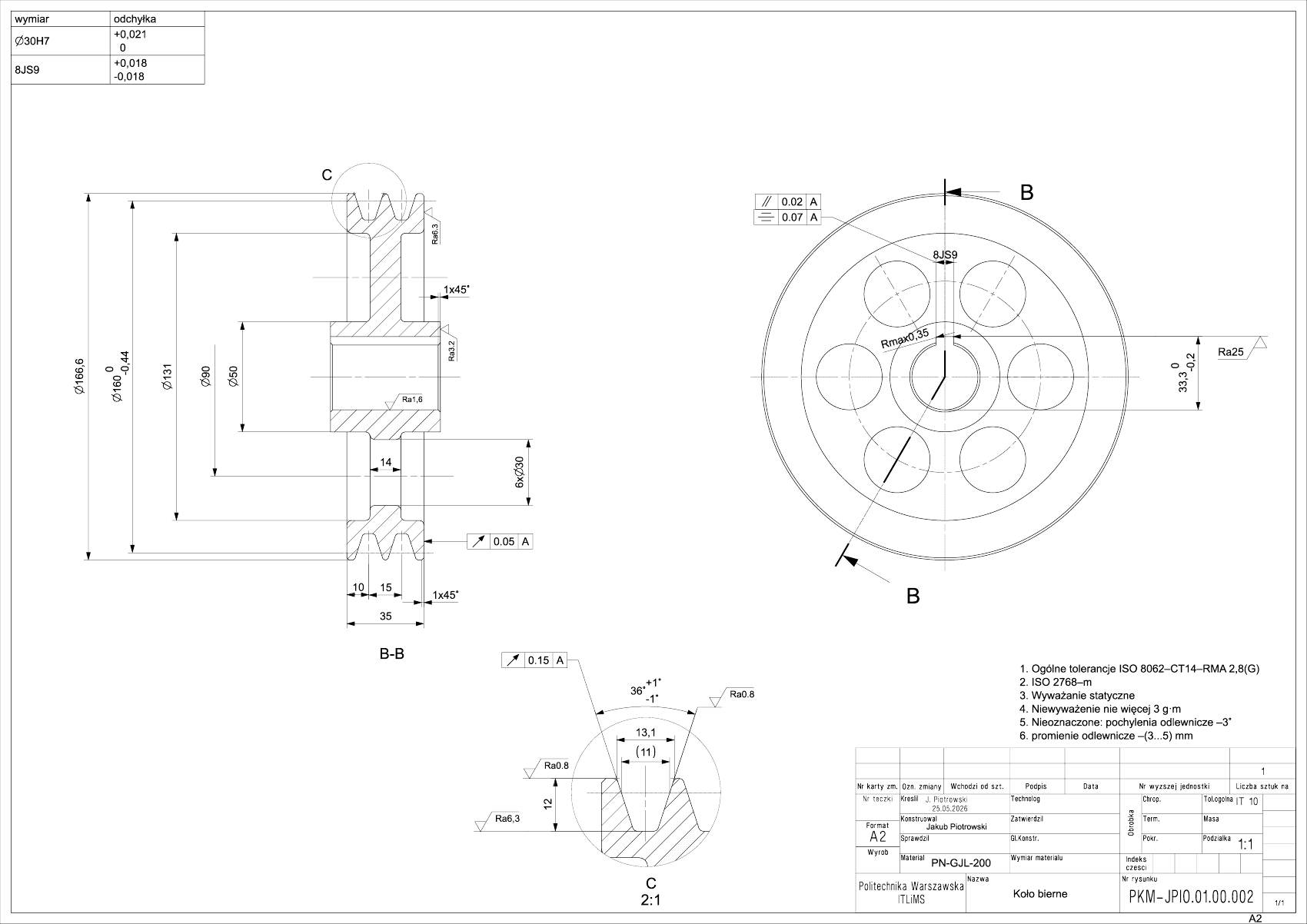
The assembly drawing is on an A0 sheet, with sections A-A and B-B and a 41-item bill of materials. The shaft and driven pulley detail drawings are fully toleranced: fits (Ø42k6, Ø35k6, Ø30d6, 8H9, 12P9, Ø4H7), geometric tolerances (concentricity 0.002, runout 0.007, perpendicularity 0.004, parallelism 0.02), surface finish (Ra 0.8 / 3.2 / 6.3) and a hardness of 170–190 HB. Untoleranced dimensions follow ISO 2768-m.
- Design calculations (20 pages, in Polish)
- A0 assembly drawing
- Drive shaft detail drawing
- Driven pulley detail drawing
Tools
Siemens NX (3D modelling, technical drawing) · LaTeX · SKF catalogues
Results gallery